Ultima Oil Pump Manual
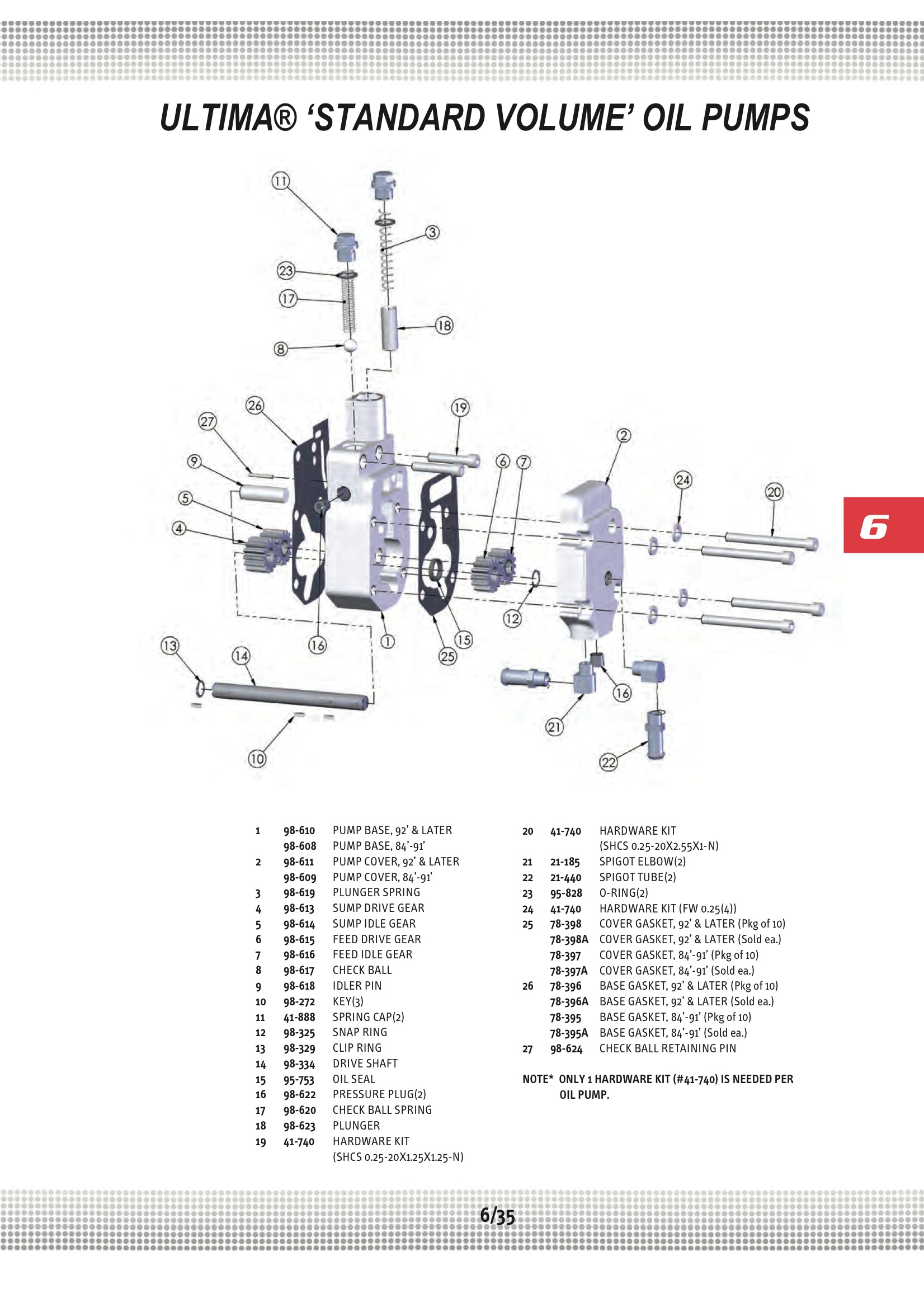
49 21-123 Oil tank vent 63533-41 Sold each 50 98-625 Base gasket 92 & ltr Sold each 51 98-627 Cover gasket 92 & Ltr Sold each 52 98-602 Pump base H.O. Sold each 53 98-603 Pump cover H.O. Sold each 54 41-740 Oil pump hardware kit. My oil pump leaked pretty well straight away on my brute, i just changed the outer gasket with a james paper type gasket and it doesnt leak any more, the gasket between the pump and the case still leaks, its a bit more drama to change so im gonna wait till winter to do it, the oil pump gaskets are metal and i personaly think the paper type gasket is better, i dont think i would sand the.
- Ultima Oil Pump Manual Briggs And Stratton
- Ultima Oil Pump Manuals
- Ultima Oil Pump Harley
- Ultima Oil Pump Reviews
Removal and Installation
REMOVAL
1. Remove the timing chain. Refer to EM-163, 'Removal'.
Ultima®Shovelhead engines use a 1992 & later style oil pump as shown in Figure 2. The feed line is mounted in the center of the outer cover of the pump and is pointing up. PERFORMANCE OIL PUMPS PERFORMANCE OIL PUMP GUIDE High volume performance upgrade for M-55HV. 25% increase in volume over stock oil pump. The 10550 housing and cover are CNC machined and phosphate coated. The lower pressure spring is included to reduce pressure if desired. Includes intermediate shaft with steel guide. Built with billet steel gears.
2. Remove oil pump assembly.
INSTALLATION
Installation is in the reverse order of removal.
Disassembly and Assembly
1. Oil pump housing
2. Outer rotor Shaun of the dead full movie download 480p.
3. Inner rotor
4. Oil pump cover
5. O-ring
6. Regulator valve set
7. Regulator valve
8. Spring
9. Regulator plug

10. Oil strainer
CAUTION: Before assembly apply new engine oil to the parts as shown above.
DISASSEMBLY
1. Remove the oil pump cover.
2. Remove inner rotor and outer rotor from oil pump housing.
3. Remove oil strainer from oil pump housing.
4. After removing regulator plug, remove spring and regulator valve.
Paralucent font free. Explore Paralucent designed by Rian Hughes at Adobe Fonts. A typeface with 35 styles, available from Adobe Fonts for sync and web use. Adobe Fonts is the easiest way to bring great type into your workflow, wherever you are. Paralucent Free Download. OnlineWebFonts.COM is Internet most popular font online download website,offers more than 8,000,000 desktop and Web font products for.
INSPECTION AFTER DISASSEMBLY
Clearance of Oil Pump Parts
• Measure clearance with feeler gauge.
• Clearance between outer rotor and oil pump body (position 1).
Standard : 0.114 - 0.260 mm (0.0045 - 0.0102 in)
• Tip clearance between inner rotor and outer rotor (position 2).
Standard : Below 0.180 mm (0.0071 in)
• Measure clearance with feeler gauge and straightedge.
• Side clearance between inner rotor and oil pump body (position 3).
Standard : 0.030 - 0.070 mm (0.0012 - 0.0028 in)
• Side clearance between outer rotor and oil pump body (position 4).
Standard : 0.050 - 0.110 mm (0.0020 - 0.0043 in)
• Calculate the clearance between inner rotor and oil pump body as follows.
1. Measure the outer diameter of protruded portion of inner rotor (position A).
2. Measure the inner diameter of oil pump body with inside micrometer (position B).
(clearance 5) = (inner diameter of oil pump body B) – (outer diameter of inner rotor A)
Standard : 0.045 - 0.091 mm (0.0018 - 0.0036 in)
Regulator Valve
1. Visually inspect components for wear and damage.
2. Check oil pressure regulator valve sliding surface and valve spring.
3. Coat regulator valve with engine oil. Check that it falls smoothly into the valve hole by its own weight.
If damaged, replace regulator valve set or oil pump body.
Regulator Valve Clearance
(Clearance 6) = D (Valve hole diameter) – E (Outer diameter of valve)
Standard : 0.040 - 0.097 mm (0.0016 - 0.0038 in)
If it exceeds the standard, replace the oil pump body.
CAUTION: Coat regulator valve with engine oil.
Check that it falls smoothly into the valve hole by its own weight.
Assembly
Assembly is in the reverse order of disassembly.
• Assemble the inner rotor and outer rotor with the punched marks on the oil pump cover side.
CAUTION: Before assembly apply new engine oil to the parts as specified.
Oil cooler
Removal and Installation 1. Oil filter 2. Oil cooler bolt 3. Water pipe 4. Water hose 5. Oil cooler 6. O-ring 7. Oil pan 8. Water pipe 9. Relief valve 10. Water drain plug 11. Copper gask ..Other materials:
Checking bulbs
With all doors closed, apply the parking brake and place the ignition switch to the ON position without starting the engine. The following lights will come on: The following lights (if equipped) come on briefly and then go off: If any light fails to come on, it may indicate a burned-out b ..
Door speaker (coupe)
Description The audio unit sends audio signals to the BOSE speaker amp. The BOSE speaker amp. amplifies the audio signals before sending them to the door speakers using the audio signal circuits. Diagnosis Procedure 1.HARNESS CHECK 1. Disconnect BOSE speaker amp. connector B121 and suspec ..
B2190, P1610 nats antenna amp
Description Performs ID verification through BCM and keyfob when push-button ignition switch is pressed. Prohibits the release of steering lock or start of engine when an unregistered ID of keyfob is used. DTC Logic DTC DETECTION LOGIC DTC CONFIRMATION PROCEDURE 1.PERFORM DTC CONFIRMA ..
Removal and Installation
REMOVAL
1. Remove the timing chain. Refer to EM-163, 'Removal'.
2. Remove oil pump assembly.
INSTALLATION
Installation is in the reverse order of removal.
Disassembly and Assembly
1. Oil pump housing
2. Outer rotor
3. Inner rotor
4. Oil pump cover
5. O-ring
6. Regulator valve set
7. Regulator valve
8. Spring
9. Regulator plug
10. Oil strainer
CAUTION: Before assembly apply new engine oil to the parts as shown above.
DISASSEMBLY
1. Remove the oil pump cover.
2. Remove inner rotor and outer rotor from oil pump housing.
3. Remove oil strainer from oil pump housing.
4. After removing regulator plug, remove spring and regulator valve.
INSPECTION AFTER DISASSEMBLY
Clearance of Oil Pump Parts
Ultima Oil Pump Manual Briggs And Stratton
• Measure clearance with feeler gauge.

• Clearance between outer rotor and oil pump body (position 1).
Standard : 0.114 - 0.260 mm (0.0045 - 0.0102 in)
• Tip clearance between inner rotor and outer rotor (position 2).
Standard : Below 0.180 mm (0.0071 in)
• Measure clearance with feeler gauge and straightedge.
• Side clearance between inner rotor and oil pump body (position 3).
Standard : 0.030 - 0.070 mm (0.0012 - 0.0028 in)
• Side clearance between outer rotor and oil pump body (position 4).
Standard : 0.050 - 0.110 mm (0.0020 - 0.0043 in)
• Calculate the clearance between inner rotor and oil pump body as follows.
1. Measure the outer diameter of protruded portion of inner rotor (position A).
2. Measure the inner diameter of oil pump body with inside micrometer (position B).
(clearance 5) = (inner diameter of oil pump body B) – (outer diameter of inner rotor A)
Ultima Oil Pump Manuals
Standard : 0.045 - 0.091 mm (0.0018 - 0.0036 in)
Regulator Valve
1. Visually inspect components for wear and damage.
2. Check oil pressure regulator valve sliding surface and valve spring.
3. Coat regulator valve with engine oil. Check that it falls smoothly into the valve hole by its own weight.
If damaged, replace regulator valve set or oil pump body.
Regulator Valve Clearance
(Clearance 6) = D (Valve hole diameter) – E (Outer diameter of valve)
Standard : 0.040 - 0.097 mm (0.0016 - 0.0038 in)
If it exceeds the standard, replace the oil pump body.
CAUTION: Coat regulator valve with engine oil.
Check that it falls smoothly into the valve hole by its own weight.
Assembly
Assembly is in the reverse order of disassembly.
• Assemble the inner rotor and outer rotor with the punched marks on the oil pump cover side.
CAUTION: Before assembly apply new engine oil to the parts as specified.
Ultima Oil Pump Harley
Oil cooler
Removal and Installation 1. Oil filter 2. Oil cooler bolt 3. Water pipe 4. Water hose 5. Oil cooler 6. O-ring 7. Oil pan 8. Water pipe 9. Relief valve 10. Water drain plug 11. Copper gask ..Other materials:

Ultima Oil Pump Reviews
P1726 electric throttle control system
Description Electric throttle control actuator consists of throttle control motor, accelerator pedal position sensor, throttle position sensor etc. The actuator sends a signal to the ECM, and ECM sends the signal to TCM with CAN communication. DTC Logic DTC DETECTION LOGIC DTC CONFIRMAT ..
P2118 throttle control motor
Description The throttle control motor is operated by the ECM and it opens and closes the throttle valve. The current opening angle of the throttle valve is detected by the throttle position sensor and it provides feedback to the ECM to control the throttle control motor to make the thrott ..
Corrosion protection
Description To provide improved corrosion prevention, the following anti-corrosive measures have been implemented in NISSAN production plants. When repairing or replacing body panels, it is necessary to use the same anti-corrosive measures. Anti-Corrosive Precoated Steel (Galvannealed Steel) ..